What is FPDs?
- Types of FPDs
- Basic structure of a LCD
- Principle of a LCD (The light shutter effect)
- Contrast ratio of LCDs
Types of FPDs

There are several types of FPDs according to the way they display images, such as liquid crystal displays (LCDs), organic light emitting diodes (OLEDs), and light emitting diode (LED) displays. The FPDs we have today have reached a considerably high performance level and are very multi-functionalized. However, it had various technical problems at the beginning of release such as high power consumption, low transmittance, and weak color strength. To handle these drawbacks, each manufacturer began developing various FPDs in various methods.
Types of Display Devices

Basic structure of a LCD
A liquid crystal display is a type of FPD which displays images using the unique property of liquid crystals. The liquid crystal is an intermediate material between solid (crystal) and liquid, and its molecular arrangement can be changed by applying voltage.
Internal structure of a LCD
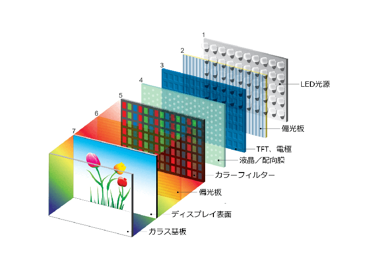
Cross-sectional view of a LCD
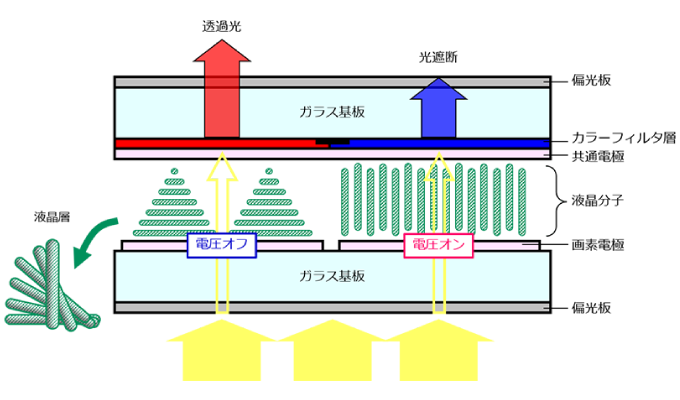
The figure below is a cross-sectional diagram of a LCD. The images displayed on the screen are expressed by a combination of tiny dots of color called pixels. These pixels are composed of three subpixels; R, G, and B (Red, Green and Blue), and to each sub pixel corresponds one small electrode. When a certain voltage is applied through these electrodes, it locally changes the molecular arrangement of the liquid crystal and controls whether light is blocked or transmitted through the corresponding section. By using the liquid crystal as a “shutter” and adjusting the transmission of light, we are able to expresses various colors and gradations on the screen.
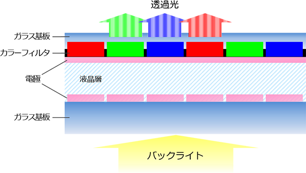
Principle of a LCD (The light shutter effect)
In order to express images colorfully, it is necessary to adjust the amount of light transmitted through the color filter. Here, the polarization of light becomes very important. LCDs possess several functions to adjust the polarization of light and are able to change the amount of light that is transmitted at will, therefore capable of expressing colorful images.
Function 1: The light shutter function of a polarizer
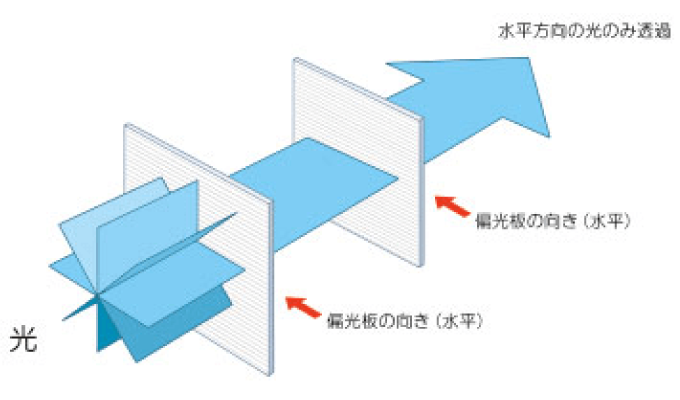
When two polarizing plates are set horizontally
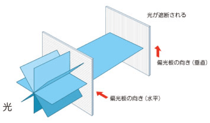
When one polarizing plate is installed vertically
Control of screen brightness by using polarizers
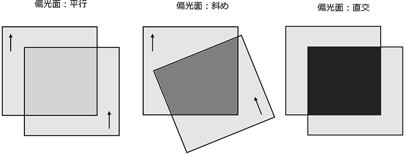
Function 2: Arrangement of liquid crystal molecules using the alignment layer
However, in an actual LCD, the angles of the polarizers are fixed and cannot be rotated. So we need to adjust the polarization of light by controlling the liquid crystal layer located in the middle of the display.
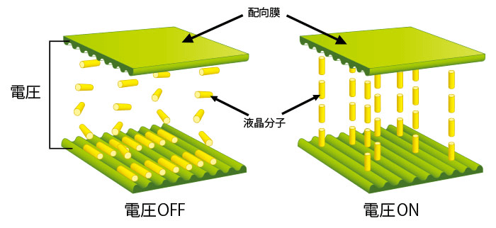
As described above, a liquid crystal is the intermediate state between a solid (crystal) and a liquid. Molecules of this liquid crystal are arranged with a crude regularity, however, when a furrowed plate is placed nearby, the molecules line up regularly according to the direction of the furrows (diagram below). This furrowed plate is called the “alignment layer” and are inserted on each side of the liquid crystal.
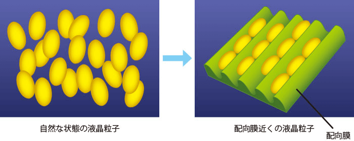
Function 3: Adjustment of liquid crystal molecules by voltage
In addition to the combination of polarizers and alignment layers, voltage is also used to control the liquid crystal molecules and adjust the amount of light that is transmitted. Let's take a closer look of what is actually going on step by step (Note: The following is only one example).
First, the two polarizers set at both sides of the display will be set orthogonally (tilted 90 degrees to one another). With just this, the light emitted from the backlight (light source) cannot pass through the display. Therefore the alignment layer is used to change the polarization of the light. Two alignment layers attached on both sides of the liquid crystal layer are set orthogonally just like the polarizers. Here, the liquid crystal molecules between the alignment layers are arranged in a characteristic manner. The molecules near the first alignment layer are arranged in the same direction as the alignment layers furrows, but as the molecules become closer to the second alignment layer, they gradually tilt to match the direction of the furrows in the second alignment layer, forming a 90 degree helical formation between the two layers. As a result, the vibration of the wave of light passing through the liquid crystal layer is also twisted 90 degrees so it can pass through the second polarizer.
Principle of the light shutter
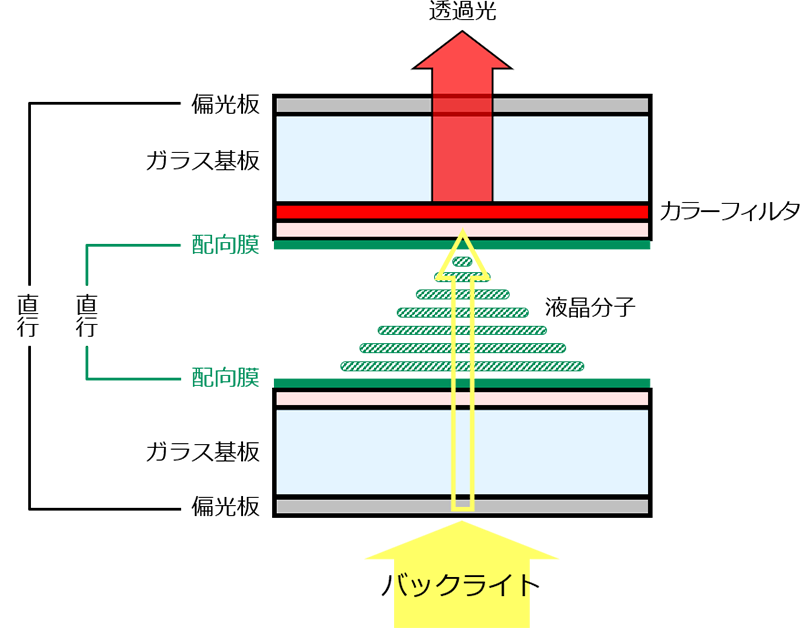
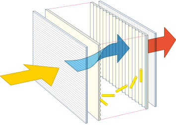
Arrangement change of liquid crystal molecules by applying voltage
Diagram of arrangement change of liquid crystal molecules
Contrast ratio of LCDs
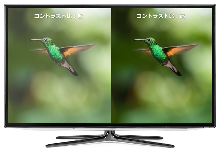
Another important factor in expressing an image beautifully is the contrast ratio. The contrast ratio is the difference of brightness between the brightest part (white display) and the darkest part (black display) on the screen.
The light emitted from the backlight takes on an arbitrary color (red, green, blue) by passing through the color filter, but during this process, some of the light is scattered by pigment particles present in the color filter. This scattering shifts the direction of the light. Consequently, in white display, a portion of the scattered light cannot pass through the second polarizing plate, resulting in reduced brightness. On the other hand, in black display, a portion of the scattered light passes through the second polarizing plate, causing light leakage. In other words, the more light is diffused by pigment particles, the lower the contrast ratio becomes, resulting in an overall dull and undefined screen.
Difference according to contrast ratio
In order to improve this, we recommend the use of a high contrast type color resist. While improving the brightness of the color filter, light leakage shall be reduced, giving a high contrast ratio and resulting in a more vibrant display.
Inquiries
TOYO VISUAL SOLUTIONS CO., LTD.
TEL:+81-3-3272-3457
